This section describes additional hardware elements involved in the mission architecture and development of the IMRS.
11.1. Mars Surface Habitat
The purpose of the Mars Surface Habitat (SHAB) is to healthfully accommodate crews of up to six astronauts at a time on the surface of Mars for about 1.5 years. It must incorporate sleeping quarters, food preparation facilities, workstations, laboratories and other work areas, bathroom, medical facilities, subsystems for ECLSS, power, communications and computing, an airlock, and storage for food, water, air, marssuits, personal effects and other items.
As the THAB is based on a Bigelow Aerospace B330 optimised for interplanetary space, so the SHAB is based on a B330 optimised for use on the surface of Mars. The B330 modules provide radiation protection comparable to the ISS, which will protect the crew during their stay and obviate the need to cover the habitat in dirt to provide additional protection (a process often recommended for Mars habitats, but one that would be challenging). A B330 module is well-suited for this purpose, yet should be much cheaper than a custom-built unit, being a COTS item, although some customisation is inevitable.
An important advantage is gained by using the same habitat technology — the B330 — for both the THAB and the SHAB; namely, commonality of hardware. It means there will be fewer systems for the crew to learn and understand. If they can repair the THAB they’ll also be able to repair the SHAB, should the need arise.
11.1.1. Entry, Descent and Landing
A B330 module weighs approximately 20-23 tonnes, which necessitates a SHLLV in order to deliver one to the surface of Mars. Reducing this mass would almost certainly require reducing the crew size, simply because of the amount of equipment and supplies necessary to keep people in good health for this length of time. Most estimates for Mars habitats exceed 20 tonnes. The B330 is a comparatively light option yet providing ample living volume.
Blue Dragon, like most Mars mission architectures, is reliant on the availability of a suitable SHLLV. It’s possible there will be a choice of several such vehicles available in the desired time frame:
- Space Launch System, currently being developed by NASA.
- Long March 9, being studied by CNSA.
- The new megalauncher planned by Roscosmos.
- Mars Colonial Transport in development at SpaceX.
For now, the SLS 130t Cargo is considered the most suitable near-term vehicle for delivering payloads of 20-30 tonnes to the surface of Mars, being the furthest along in its development. If an SLS can deliver 30 tonnes to Mars, a mass budget of about 7-10 tonnes of supplies and equipment may be sent along with the habitat. Because the total quantity of supplies and equipment required by a crew will likely exceed this amount, additional tonnage would be delivered with the Red Dragon “Mars Supply Capsules”.
After the first couple of missions, when SHABs are being reused by subsequent crews, ongoing resupply may also be achieved using capsules, or newer vehicles such as the MCT.
11.1.2. Orientation
For the basic form of the SHAB, previous architectures such as Mars Direct have primarily focused on a squat, two-or three-floor vertical cylinder, or the so-called “tuna can” model. This has become the traditional de-facto design:
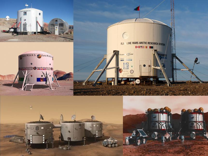
These habitats nominally have a diameter of around 8 metres, which fits neatly inside the 8.4 metre diameter payload fairing of an SLS rocket.
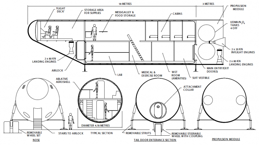
One notable exception is the MARS-Oz habitat design:
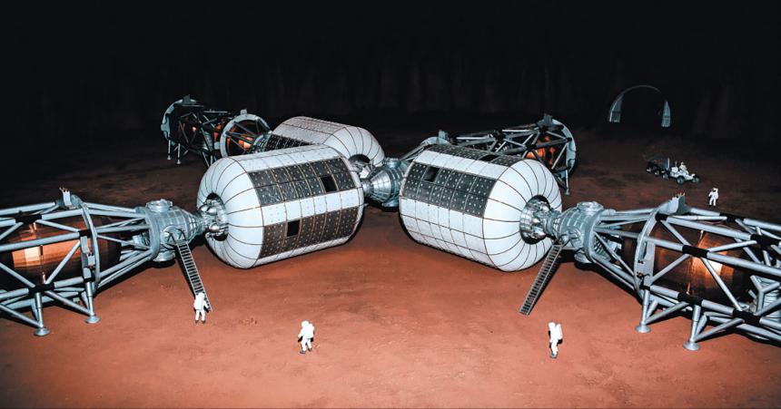
Although a B330 may seem ideal for vertical orientation like the tuna-can design, because the airlock is at the end, it is more useful if oriented horizontally. This model of a Mars base constructed from B330 modules illustrates a horizontal configuration for the modules:
11.1.3. Initialisation
The SHAB will be sent to Mars at the same time as the MAV, and possibly travel on a slow 9-month trajectory like the supply capsules. The SHAB will not land too close to the MAV, but approximately several hundred metres distant so that the launch of the MAV does not adversely affect any of the SHAB’s systems; for example, by overheating anything with rocket exhaust, or covering the SHAB’s solar panels in dust.
Once successfully landed on Mars, the SHAB will be remotely activated and several processes initiated:
- Rolls of PV material will be extracted and unrolled with the help of the CAMPER or other mobile robot, and the power system activated.
- The ISAP unit will be activated, and production of O2 and buffer gas will commence. If the SHAB is not delivered in a fully inflated state, then it will be inflated using this air.
- Water tanks will begin to be filled by the ISWP system.
11.1.4. Redundancy and Safety
One of the advantages of Blue Dragon is that, theoretically, only one habitat needs to be delivered to Mars, which can then be used for multiple missions.
In practice, however, a minimum of two habitats will be preferable in order to provide one or more backups. Blue Dragon provides every crew with a backup SHAB from the very first mission. The first SHAB (SHAB-1) is sent in the predeployment phase for the Alfa Mission, scheduled for 2031, and will therefore have been activated, tested and filled with air and water in preparation for the arrival of Alfa Crew approximately 2 years after. Note, however, that the launch opportunity for the Alfa Crew outbound trip in 2033 is the same as for the predeployment phase of Bravo Mission. Hence, the second SHAB (SHAB-2) will be en route to Mars at the same time as Alfa Crew, along with the second MAV and other equipment required for Bravo Mission.
Most of the equipment being predeployed for Bravo Mission will be travelling on a slower, 9-month trajectory, to conserve propellant, while Alfa Crew will be travelling on a quicker 6-month trajectory, to protect their health. However, SHAB-2 could also be sent on a fast trajectory in order to ensure that Alfa Crew has a backup SHAB. When SHAB-2 arrives at the IMRS, they can monitor its arrival and setup. Once its systems are fully operational, Alfa Crew will have an alternate home in SHAB-2 should there be any malfunction with SHAB-1 during their surface mission. Assuming that the two SHABs are well-maintained during their lifetime, subsequent missions will have a spare SHAB available if necessary.
Another approach would be to send SHAB-1 and SHAB-2 to Mars at the same time, and Alfa Crew can ensure that both are fully operational in preparation for future crews.
Assuming that the crew size for IMRS missions remains constant at six, only two SHABs are required for the IMRS: one for the crew, and one spare. The cash saved by not having to predeploy an SHAB from the third mission onwards can be funnelled into other base hardware such as greenhouses, power systems, heavy machinery and other components.
Having said that, the intention is that the base will expand as space technology improves and its cost decreases, participating space agencies seek to expand their activities on Mars, and some astronauts opt to remain for multiple seasons at a stretch or even permanently on Mars. It may be desirable to construct MTVs like Athena with two B330 modules (or perhaps one B2100 module) in order to support larger crews. This will require a matching habitat capacity on the surface.
In lieu of a backup SHAB, the CAMPER, which has capacity for six, may also be used as an emergency lifeboat if necessary. If both SHABs become unusable, the crew can use the CAMPER to reach the MAV and launch and transfer to Adeona, which will have contingency supplies of food and water. There they can wait until the next opportunity to head home.
11.2. Surface Vehicles
The intention is that a single payload of surface vehicles be delivered to Mars using a Falcon Heavy, which is capable of delivering an estimated 13 tonnes to the surface of Mars. This payload would include:
- The CAMPER: a large pressurised robotic vehicle with a 2-person airlock and capacity for six astronauts.
- Attachments for the CAMPER such as a drill, excavator bucket, and trailer.
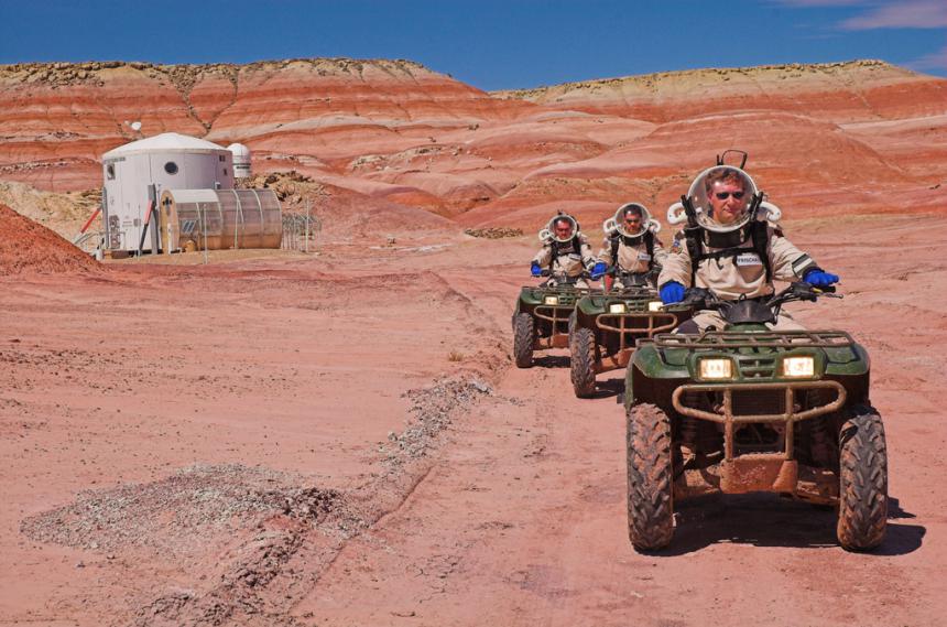
- Three unpressurised ATVs (All-Terrain Vehicle).
11.2.1. Crewed Adaptable Multipurpose Pressurised Exploration Rover
The architecture calls for a highly capable, multipurpose pressurised surface vehicle, capable of operation in both crewed and autonomous modes. This versatile vehicle will be central to the surface mission from beginning to end.
The CAMPER will fulfil a variety of functions:
- On arrival, the CAMPER will explore the surrounding environment finding safe pathways between base components, namely the SHAB, Einstein’s LZ, and the MAV.
- The CAMPER may assist the MAV and the SHAB in deployment of their photovoltaic blankets (unless this can be more effectively achieved using the AWESOM robot, a crew member, or other method).
- The CAMPER will pick up the crew from Einstein’s LZ when they first arrive, then transport them to the SHAB.
- If an excavator attachment is included, the CAMPER can clear makeshift roads between different areas of the base.
- The CAMPER will be used on a regular basis for exploring the surrounding territory, both for short, local sojourns, and longer, overnight or multisol excursions.
- At the end of the surface mission, the CAMPER will transport the crew and their samples from the SHAB to the MAV.
- It can be used as an emergency “lifeboat” in the event of an ECLSS failure in the SHAB (if a backup SHAB is unavailable).
Design
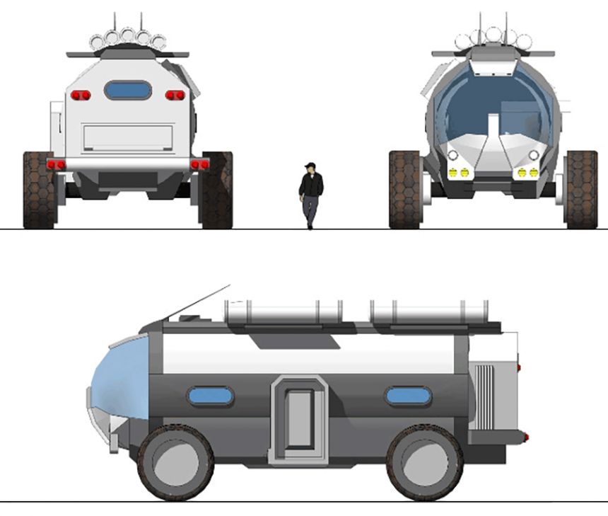
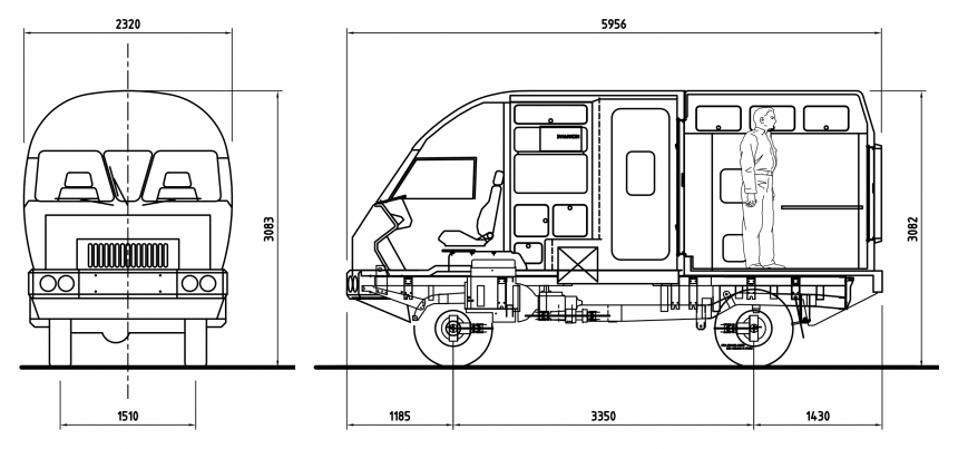
Rather than presenting a completed design, this section simply offers a handful of ideas that may influence a future design study of the CAMPER. Many designs have been proposed for Mars pressurised surface vehicles, which give an indication of what the CAMPER may look like.
The Manchu Rover, shown below, is probably somewhat larger than the CAMPER needs to be.
In contrast, the “Marsupial Rover” designed by Graham Mann and David Willson from MSA (Mars Society Australia), shown below is possibly somewhat too small, as the CAMPER must be able to seat a full crew of six. The Marsupial Rover is part of the MARS-Oz architecture developed by Mann, Willson and Jonathan Clarke, and manufacture of a prototype is almost complete.
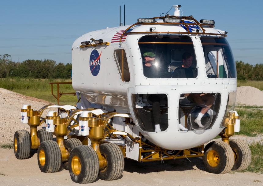
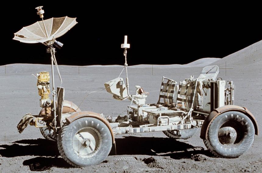
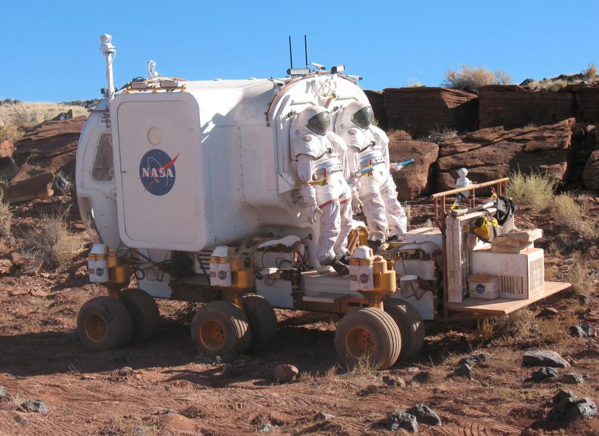
Below is shown NASA’s current prototype for a lunar vehicle known as the “small pressurized rover”, which will no doubt inform future designs for a Mars pressurised vehicle.
Capacity
Since the CAMPER picks up the whole crew from Einstein’s LZ on their arrival, and again transport the whole crew to the MAV for their departure, it must have capacity for the entire crew of six. Because standing may be difficult after spending months in microgravity, it is necessary to provide some kind of seating for all of them.
However, carrying six will be the exception rather than the norm. A typical excursion will only involve two or three crew members, and the spare seats can be converted into beds for longer excursions.
Communications
The CAMPER will constantly report its current position and condition to the SHAB, where the control room is located. This information will include the internal atmospheric pressure and constituents, internal temperature, and supplies of oxygen, buffer gas, water, food, and propellant and/or electrical energy. In this way the CAMPER can be monitored remotely, whether occupied or not. Astronauts at the SHAB will have real-time awareness of its condition at all times, including while other crew members are out exploring.
Power system
The CAMPER will most likely be solar-electric, with electric motors and high-efficiency PV panels on the roof. The vehicle will be fitted with an electricity regulator that will preferentially use solar energy, with surplus energy being stored in batteries or graphene supercapacitors.
Electric vehicle technology is currently receiving considerable investment by the automobile industry, and advancing rapidly. Battery technology in particular has improved considerably in recent years, especially since the emergence of Tesla Motors.
Batteries or supercapacitors will provide additional power when necessary, for example, at times of low solar energy (i.e. at dusk or at times of high dust), or when the excavator bucket is attached, heavy lifting is required, transporting cargo or navigating difficult terrain. When the CAMPER is not in use, solar energy will charge the batteries or supercapacitors. Although the CAMPER should not be used in low light levels purely for safety reasons, it should nonetheless be able to operate from 100% battery power if necessary.
Alternatively, or additionally, the CAMPER may have a methalox combustion engine. As described in Case for Mars (Zubrin & Wagner, 1996), combustion-powered surface vehicles may be the most effective way to cover long distances on Mars and thereby explore a larger area around the base. Methalox is the best propellant for combustion engines on Mars due to its high energy-mass ratio, ease of storage and transportation, and the fact that it can be manufactured from local resources.
If this option is taken, the MAV could be designed to produce a surplus of propellant that could be used by the CAMPER, as in Mars Direct. This would require the MAV to have larger tanks, which would increase its mass, and might compromise the common descent-ascent stage design described earlier. Another approach would be for the CAMPER to have a built-in, smaller-scale ISPP system, but then the obvious question is how it would be powered. Yet another approach would be for the SHAB to include an ISPP system, similar to the MAV’s, which would manufacture methalox for the CAMPER.
Airlock and dust mitigation
Unlike some modern pressurised Mars rover designs, the CAMPER will not have suitports, for several reasons:
- The intention is to use MCP spacesuits, which are not compatible with suitports.
- Gas pressurised suits with suitports would be too bulky to wear inside the Dragon capsules.
- The CAMPER must have capacity for the entire crew and it would be impractical to include six suitports.
Instead, the CAMPER will have an airlock. In the interests of efficiently balancing time and volume, this airlock will accommodate up to two people at once, as this will be the most common excursion crew size, and crew members can help clean each other’s suits during ingress (see below). For the whole crew to enter or exit, as is necessary at the beginning and end of the surface mission, the airlock will therefore need to be cycled three times to transfer all six crew members.
For more on this topic, refer to the sections below about Marssuits and Airlocks.
Marssuit support
The intention is that the astronauts will be able to wear their marssuits inside the vehicle, since they will need to be wearing them before entering and after exiting the vehicle. However, the CAMPER will also include racks along one wall for hanging up PLSS backpacks and helmets, and sockets for plugging in suit batteries for recharging from the CAMPER’s power system.
The CAMPER will be capable of supporting extended, multi-sol excursions to more distant locations. Storage for marssuits as well as casual clothes will be provided.
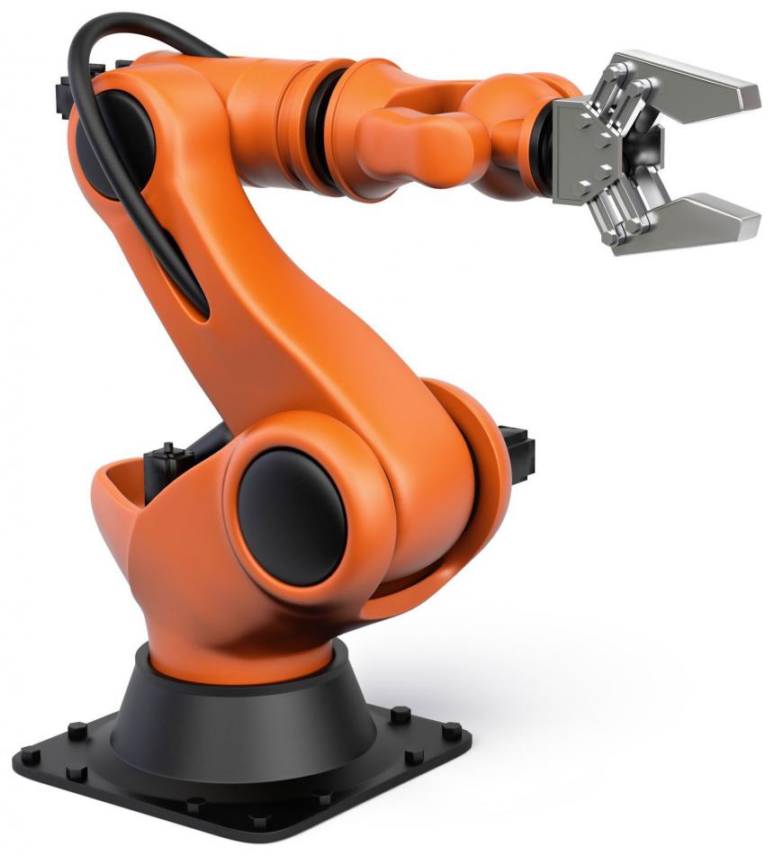
Robotic arms and manipulators
The CAMPER is actually a robot, and will have two powerful arms, one on each side, which can be controlled from within the vehicle, from the SHAB, or remotely by MCC on Earth.
The arms will have grippers that may be used for several purposes:
- Picking up samples of dust and rock, and placing these in sample boxes along the sides of the CAMPER. This will enable crew members to collect samples without leaving the vehicle.
- Picking up heavy pieces of equipment or cargo for moving. For example, carrying cargo from supply capsules back to the SHAB.
- Gripping and moving an excavator bucket.
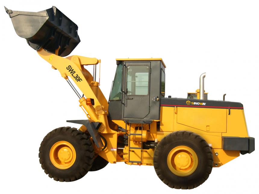
Excavator capability
An excavation attachment may be included for clearing makeshift roads, piling loose regolith on a habitat for additional radiation protection and thermal insulation (not that that should be necessary with the B330 modules), or uncovering deeper layers of regolith for closer inspection.
This equipment should be easily attached or detached. A bucket similar to that found on an excavator or front-end loader could be fitted with handles that can be gripped by the grippers on the CAMPER’s arms.
One issue with this feature is that the CAMPER needs to remain stable while using it. If it’s too light in the back end then carrying the bucket may cause it to tip forwards, particularly when loaded. This problem may be addressed by distributing the bulk of the vehicle’s mass (for example, battery packs and ECLSS) towards the rear of the vehicle, as is customary with ordinary bobcats and front-end loaders. Another approach is to use tracks instead of wheels.
Tracks
In order to provide greater stability for the rover when using the excavator attachment or the drill, tank tracks may be preferable to wheels.
Tracks are especially good for traction and will help to prevent the CAMPER from becoming stuck in soft soil, as happened with Spirit.
Drill
The CAMPER may also be fitted with a drill suitable for taking core samples. This feature supports the science objectives of the mission, including the search for water, volatiles and biological life, and the investigation of subsurface mineralogy.
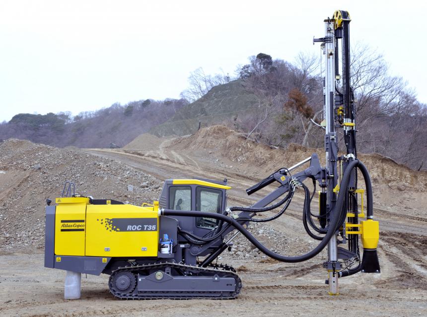
The purpose and design of the drill are based on the core objectives of the Ice Dragon mission (Stoker et al. 2012), which proposes to land a Red Dragon capsule that contains within it a drill for taking core samples (see SpaceX Dragon Capsule). Although the Ice Dragon has not yet been approved, its scientific and engineering objectives remain relevant and practical, and can be incorporated into one or more IMRS missions by the inclusion of a drill capable of penetrating at least two metres into the Martian permafrost.
Aside from investigating subsurface water and organics, a drill will reveal information about the availability of elements in Mars’s near-surface crust such as metals and the elements necessary for plant growth. This is important for settlement, as metals are valuable for manufacturing and construction, and plant nutrients are necessary for food production and terraforming. Investigation of the subsurface environment will also provide interesting insights into Mars’s areological history.
Available hardware
As one of the cost-reduction strategies employed in the IMRS plan is to make use of COTS hardware where possible, it’s worthwhile to investigate if any vehicles already exist that could be a suitable prototype for the CAMPER.
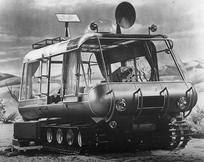
One such vehicle could be the Viking BsV 10 All Terrain Vehicle (Protected) developed for the Royal Marines by Hägglunds Vehicle AB and the UK Ministry of Defence. The Viking is an amphibious tracked vehicle with a road speed of 65 km/h and a water speed of 5 km/h. Each of the four rubber tracks are driven by the powerful diesel engine, enabling it to effectively traverse all types of terrain.
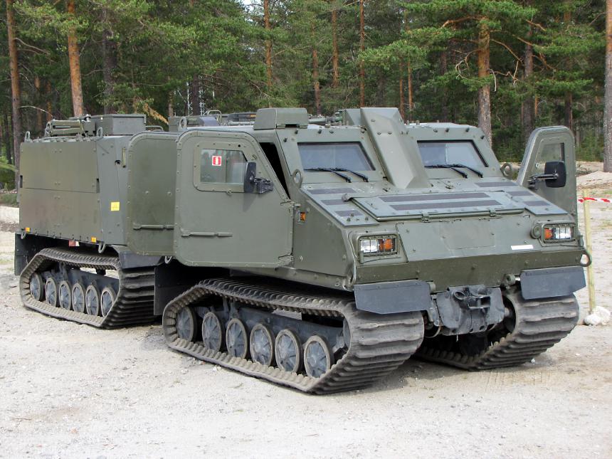
The Viking design includes several features that will be useful on Mars. Although a Mars rover doesn’t need to be amphibious, this aspect of the Viking’s design implies that the vehicle is at least somewhat airtight, which will be important for the pressurised CAMPER. It’s also very tough and mobile, having been designed for use in jungle, desert and polar conditions. With an operating temperature range from -46°C to 49°C the Viking therefore includes heaters, which will also be an essential feature of the CAMPER, although slightly more powerful heaters will be necessary at the IMRS where the temperature will range between about -60°C and 0°C. The Viking naturally also includes integrated communications and electronics.
The vehicle has two separate sections. The front section carries the crew, with the rear section being used differently depending on the vehicle’s purpose. For example, the Troop Carrying Variant can carry up to 12 people. However, a better prototype for the CAMPER would be the Repair and Recovery Variant, in which the rear section carries a crane, mobile workshop, air compressor and capstan. In the CAMPER, the front section would be designed to carry up to six astronauts in the front section, plus the airlock and ECLSS. The rear section could be used for the drill rig, rock boxes, mobile laboratory, supplies and other things. It may be a useful feature of the CAMPER for the rear section to be detachable when not in use.
The Viking is powered by a diesel engine, which would be replaced by batteries and/or a methalox engine. The roof could be fitted with solar panels to recharge batteries and provide additional power to electronics, communications, the ECLSS and internal lighting. Although the Viking can travel up to 65 km/h on roads, a maximum speed of 10-20 km/h will be more than enough on Mars. Efficiency and safety will be much more important design goals than speed.
Ultimately something like a Viking may only serve as inspiration for the CAMPER’s design rather than a material prototype. Although it may seem cheaper to adapt an existing vehicle, the CAMPER will probably be sufficiently different that constructing an entirely new vehicle will produce a better result, especially since it will need to be built from a much lighter material than the heavy steel used in the Viking, in order to keep the mass low. However, as a large part of development cost is design, starting from an existing proven design will still produce a tangible cost saving. In addition, several subsystems (drive train, communications, controls, display, etc.) may be directly transplantable from a Viking into the CAMPER.
11.2.2. All Terrain Vehicles
Several (2-3) ATVs or UTVs (Utility Task Vehicles) will be included in the equipment predeployed to Mars for Alfa Mission. Future missions may include additional ATV/UTVs or spare parts, depending on requirements.
Each ATV will be capable of carrying 1-2 people in addition to lightweight loads such as tools, samples, supplies and experiments.

The primary purpose of ATVs is to provide convenient and accessible short-range transport for small teams (typically 2-3 people) around the region close to the base. Such uses could include:
- Brief/nearby EVAs.
- Driving between the SHAB and the MAV or Dragon capsules, or other areas of the base, to make inspections or retrieve equipment or supplies.
- Backup surface transport for emergencies.
Their advantages include:
- Low mass.
- Low energy/fuel requirements.
- Faster than walking.
- Less time delay in entering/exiting the vehicle, compared with the CAMPER, due to not having to cycle an airlock.
- Easy mount/dismount for field work, e.g. close inspection of surface features or equipment, or deployment/recovery of surface experiments.
- Capability to haul or carry light/medium-mass payloads.
ATVs may be battery or solar-powered, or they may run off methalox if the MAV’s ISPP system is configured to produce a surplus (Zubrin, Baker & Gwynne 1991).
Single-person ATVs have been used as surface vehicles in Mars analogue research at FMARS and MDRS since their construction, and have proven to be exceptionally useful.
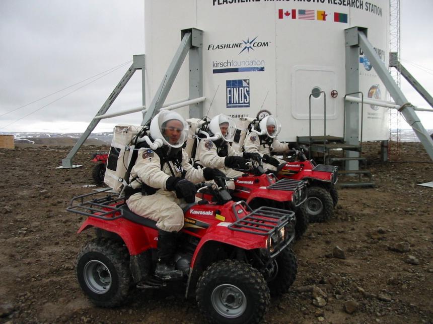
The Apollo 15 Lunar Rover bore a closer resemblance to an ATV than the pressurised vehicles now being considered for the Moon and Mars. It may be that ATVs developed for Mars will resemble the Lunar Rover, particularly if designed to accommodate two astronauts in marssuits.
11.3. Communications
Communications are fundamental to the success of IMRS. The astronauts need to be in contact with Earth, and with each other, 100% of the time. In addition, telemetry data from all spacecraft and base elements must be accessible to MCC on Earth as well as the crew on Mars.
An important consideration when designing communications solutions for HMMs is that the bandwidth requirement will be much higher than has ever been required by a robotic mission, including:
- text, voice and video messaging;
- uploading images and streaming video;
- uploading telemetry data from all capsules, vehicles, habitats and marssuits;
- uploading health data (human telemetry);
- uploading data collected during field work and from experiments;
- downloading websites, music and videos for caching on the SHAB and THAB’s proxy servers (although most of this can be done in advance).
To support the high bandwidth requirement, all in-space communications required by the mission will probably utilise lasers. Laser communication in space has been successfully demonstrated by NASA’s OPALS (Optical Payload for Lasercomm Science) and LLCD (Lunar Laser Communication Demonstration) missions, and ESA’s EDRS (European Data Relay System). OPALS and LLCD set new records for space communications data rates of 50 Mbps and 622 Mbps respectively. The EDRS “SpaceDataHighway” can support 1.8 Gbps over 45,000 km links, potentially increasing to 7.2 Gbps in the near future. Coherent bidirectional space-ground laser communication links of 5.6 Gbps have already been demonstrated.
NASA’s LCRD (Laser Communications Relay Demonstration) mission is designed for laser communications between Earth’s surface and space, and all around the Solar System. With the first satellite launching in 2017, this mission could be an important precursor to development of an Earth-Mars laser communications network.
11.3.1. Between Earth and IMRS
The IMRS will be able to communicate directly with Earth whenever there’s a direct line of sight between them. However, this is not always the case, for two reasons:
Problem 1 - Mars rotates: Because Mars is rotating on its axis, it comes between Earth and IMRS during the Martian night, blocking direct communications.
Problem 2 - solar conjunction: Approximately every 780 days Earth and Mars are on opposite sides of the Sun (Mars solar conjunction). Thermal noise from the Sun prevents direct Earth-Mars communications for about 2-4 weeks. This would occur once during each surface mission.
With no CRSes (Communications Relay Satellite), IMRS would therefore only be able to communicate with Earth about 48% of the time. This may be acceptable for robotic missions, but certainly not for human missions. People on Mars will want and need to be connected with Earth 100% of the time; not just for safety, but also psychological reasons. Back on Earth, friends, family, MCC and the media will all be depending on constant communications with the crew. Any disruption would produce stress on both planets and would greatly amplify the danger of an emergency situation on Mars.
Orbiters
The approach currently taken by robots and spacecraft on the surface of Mars to address the Mars rotation problem is to relay messages through orbiters like the 2001 Mars Odyssey, the Mars Global Surveyor and the Mars Reconnaissance Orbiter. These spacecraft are designed to double as CRSes and are much closer to the surface of Mars than Earth is, which means the signal strength required to communicate with them is significantly less. Being in orbit, they are also in sight of Earth for much longer periods of time.
This approach could be taken by the IMRS; however, there would still be times when no orbiters will be visible from the base, which would interrupt communications with Earth. Besides, the bandwidth provided by existing orbiters is far less than what will be required by the IMRS.
MCOS (Mars Communications and Observation Satellite)
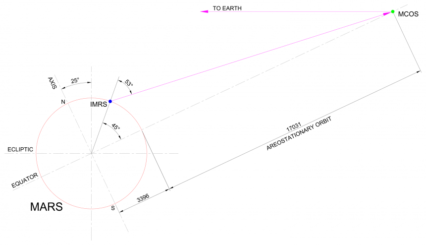
The Mars rotation problem can be almost fully addressed by placing a dedicated satellite in an areostationary orbit above the base. This is a circular orbit at an altitude of approximately 17,031 km above Mars’s equator, where it’s orbital period matches the period of Mars’s rotation, thus causing it to appear stationary with respect to the surface of Mars.
MCOS, which will be a combination of high-bandwidth LCRS (Laser Communications Relay Satellite) and high-resolution Mars observation satellite, would thus be positioned above Mars’s equator, at an equal or similar longitude to IMRS.
During the night at IMRS, when the line of sight between IMRS and Earth is blocked by Mars itself, communications will be relayed through MCOS. Because of the high altitude of the satellite (~5 times the radius of Mars), and the inclination of Mars’s axis, this capability enables communications to be relayed from IMRS towards Earth about 99% of the time. There will be occasions when MCOS, Mars and Earth will line up and Mars will block the line of sight between MCOS and Earth, but such periods will be infrequent and brief.
Streaming video from Mars
One of the advantages of an areostationary orbit is that MCOS can provide, not only communications, but also continuous observation of IMRS.
MCOS will include a high resolution colour camera comparable or superior to HiRISE (High Resolution Imaging Science Experiment), enabling the base to be monitored from orbit. This will be especially important in case of emergency. If other modes of communications break down, being able to see the IMRS from space will provide valuable clues as to the situation on the surface (a scenario described in Andy Weir’s superb novel The Martian).
Such a camera should be both cheaper and technologically superior to the $40 million HiRISE camera, due to evolution in CCD (Charged Coupled Device) and other related technology.
MCOS will ideally also provide real-time HD (High Definition) video from space. The live HD video stream of Earth from the ISS provided by UrtheCast will be instructive in the design of such a system.
With at least two cameras available, MCOS will be usable for more than simply observation of the base. It can be used for studying almost one entire side of Mars and provide advanced notice of weather conditions, such as dust storms, that could affect a mission.
A crucial benefit is that live images and video beamed direct from IMRS, from cameras on the ground as well as from MCOS, will greatly increase engagement in the mission. This, in turn, increases ROI, since the higher the level of engagement, the more people are benefiting in terms of inspiration, education, and contributing their attention to the evolution and success of humanity.
The view from MCOS won’t be straight down onto the base because it will be above the equator, whereas IMRS is more likely to be located between about 30°N and 60°N, as discussed in Site Selection. As shown in the above drawing, if IMRS is located at latitude of 45°N, the view from MCOS will be at an angle of about 53°, which is still a perfectly useful viewing angle.
It’s worth noting that the potential for an areostationary communications satellite is yet another important advantage of the “base-first” strategy, as this would not be practical if each mission was to a completely different location. However, with a plan to build up a base at a single location, it makes perfect sense. Having said that, with continuous visibility of almost 42% of the planet the MCOS could potentially serve multiple missions or bases on the same side of Mars.
MARSNET
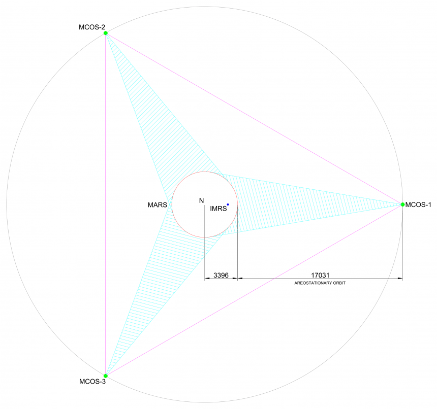
The addition of a second MCOS in aerostationary orbit at a different longitude would provide connectivity between the IMRS and Earth during those occasional brief periods when Mars blocks the line of sight between MCOS and Earth.
At those times, communications can be relayed to “MCOS-2”, and from there to Earth. In fact, by placing MCOS-2 at 120° from MCOS-1, 100% connectivity can be provided between Earth and about two-thirds of the Martian surface. Each MCOS would function as a relay for the other when required.
If there was only to be one base on Mars then it would be hard to justify the expense of a second MCOS. However, because MCOS-2 has the potential to open up another one third of the planet, in addition to enabling 100% connectivity with IMRS, it should really be added as soon as budget permits.
In fact, near global coverage of Mars can be provided by three such satellites, separated from each other by 120°. This will provide communications connectivity with Earth from almost everywhere on Mars except for the very highest latitudes (i.e. close to the poles).
Such a setup would form the early stage of a global Martian internet, or MARSNET. There’s little doubt that Martian internet will be satellite-based. Earth will have global satellite-based internet within about 5-10 years, which will drive the evolution of space-based communications.
The construction of this simple satellite network will be invaluable for ongoing exploration and settlement across the planet, capable of supporting both robotic and human missions for many years.
One potential schedule would be to deploy one MCOS with each of the first three missions. This would enable 99% connectivity with Earth from the first mission, and 100% from the second mission. From the third mission, almost all of Mars would be accessible to humans in terms of continuous communications with Earth. However, this timeline could be unnecessarily rapid in terms of budget, and the third satellite could be deployed later, when specifically required by future missions.
Mars One solution
The solution developed for Mars One (Lansdorp & Wielders 2014) to provide approximately 99% connectivity between Earth and the Mars One settlement relies on one CRS for each of the problems described earlier.
To address the problem of Mars’s rotation, the same idea of using an areostationary satellite above the base is planned.
To address the problem of solar conjunction, a satellite is to be placed at Earth’s L5 Lagrangian point (i.e. sharing Earth’s orbit, but trailing by 60°), which will relay communications around the Sun during this period.
The advantage of placing a CRS at L5 is that this is a gravitationally stable Lagrange point, which reduces or eliminates the need for station-keeping. However, this apparent benefit is a double-edged sword, because L4 and L5, being gravitationally stable, tend to attract meteoroids and micrometeoroids (space dust). At L4, which is 60° ahead of Earth in the same orbit, is the asteroid 2010 TK7, making it an Earth trojan. There are no known Earth trojans at L5, however, rocks and dust are likely, and these could potentially damage the satellite.
MARSLINK
The solar conjunction problem could perhaps be solved more effectively with a set of three HLCRSes, separated from each other by 120°, and thus forming a rotating equilateral triangle, similar to the three MCOSes around Mars. These three satellites may be referred to as MARSLINK.
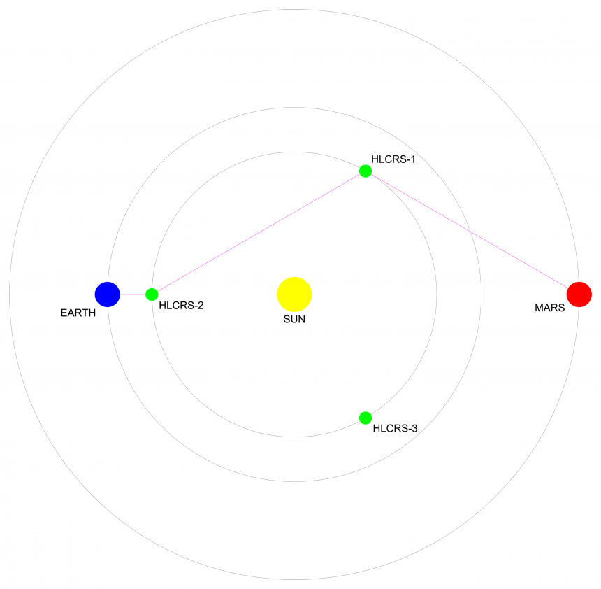
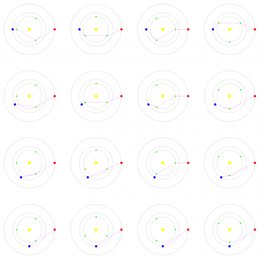
Whenever Earth and Mars are separated by more than, say, 90°, communications between the planets can be routed through one or two of these satellites. The following diagram illustrates some possible routing paths given different relative positions of Earth, Mars and the satellites.
This solution to the solar conjunction problem is more expensive than the single L5 satellite, requiring three satellites instead of one. However, the HLCRSes may not be too expensive, and there are numerous advantages to this approach:
- Less likelihood of being damaged by meteoroids.
- Maintaining a constant orbital radius is less important in this configuration, as is the satellites’ velocity. Even if a satellite’s station-keeping mechanism malfunctions and it begins changing altitude, it will not move quickly away from its original orbit (which is quite stable) and will continue to function perfectly well for many years. The satellites do not need to remain in a fixed position with respect to Earth or Mars, but only to be visible.
- Redundancy is built in. If one of the satellites goes offline for any reason, or is blocked by another object, then there is always an alternate route; either directly to the target (Earth or Mars), or the other way around the triangle.
- The satellites will be solar-powered. Being a little closer in to the Sun than Earth orbit will be advantageous for boosting signal strength.
- An unlimited number of additional satellites can be added to either the same orbit or others (including heliocentric polar orbits), in order to improve redundancy, reduce lag times, increase bandwidth, decrease transmission distances, or improve signal strength.
- The satellites will be well-positioned to connect, not only Earth and Mars, but all inner Solar System destinations, including the Moon, Venus, Mercury, NEAs, Ceres, etc.
- If so designed, the satellites could fulfil additional functions, such as solar observation or asteroid hunting. They could, in fact, serve as an early-warning system for CME’s, relaying information directly back to Mars to warn the crew in advance of impending solar events.
Orbital parameters
In the above drawings of MARSLINK, the HLCRSes are in a circular orbit at approximately 125 Gm, roughly halfway between the orbits of Venus (103 Gm) and Earth (150 Gm). This radius is optimal for minimising the longest transmission distance between Mars and the satellites. The benefit of minimising these transmission distances is that transmitters and receivers will not need to be as powerful, making them cheaper, lighter, and less power-hungry; or, alternately, the bandwidth can be greater.
However, there are other factors that could contribute to determining the ideal orbital radius. For example, Earth, with its large radio antennas, will be able to hear much fainter signals than the satellites; therefore, most of the time it will be more efficient, in terms of minimising communications lag time, for packets to be transmitted directly between Earth and Mars when practical (as shown in the lower 4 images, above).
Another factor is power. The satellites will be solar-powered, therefore, they closer they are to the Sun the more energy they will be able to harness for relaying transmissions and perhaps also for station-keeping. The transmission line-of-sight does not have to miss the Sun by much to avoid thermal noise, suggesting that the satellites could be quite close in, perhaps even inside the orbit of Venus.
The downside of being too close to the Sun is that the satellites would be exposed to a higher intensity of solar radiation and could degrade faster; also, they’ll be more greatly affected by solar radiation pressure, which will increase the amount of propellant required for station-keeping. Both of these effects would reduce the satellites’ lifetime.
In addition, the closer they are to the Sun, the faster they’ll be moving. This could increase the difficulty of targeting a steerable communications laser with accuracy. If the satellites are farther out from the Sun, they will be closer to Mars, and moving slower, which should, in theory, improve the accuracy of transmission.
Further analysis is necessary to determine the optimal orbital radius for these satellites.
MarsSat
The main problem with MARSLINK will be the mass and power requirements of the satellites, considering the large distances between them and Mars. Not only would the satellites in heliocentric orbit need to be reasonably powerful, and thus heavier and more expensive, but also the ones in Mars orbit.
A cleverer solution for maintaining Earth-Mars communications during solar conjunction could be “MarsSat” (Gangale 2006). MarsSat is a CRS occupying a heliocentric orbit with the same period as Mars, except with a slightly different eccentricity and orbital plane. This type of orbit is called a “Gangale orbit”, after its designer, Tom Gangale. Such a satellite would appear, from the perspective of Mars, to orbit Mars once per Martian year, despite being gravitationally bound to the Sun.
The benefits of MarsSat:
- As it is not located at Earth or Mars L4 or L5 points, it would not be susceptible to damage from trojan meteoroids or micrometeoroids (although naturally it would still be at risk of collision with any of the countless small objects circulating through the inner Solar System, as are all satellites and spacecraft).
- The distance between Mars and MarsSat would be on the order of 22 Gm. As this is around one tenth the maximum distance between Mars and the closest MARSLINK satellite, or one at L4/L5, the signal received by MarsSat would be around 100 times stronger. This means both the MCOS transmitting antenna and the MarsSat receiving antenna can be smaller, which translates to lower satellite masses and power requirements, and therefore lower cost.
Analysis has shown (Byford, Goppert & Gangale 2008) that the optimal configuration for an Earth-Mars communications link, in terms of mass, power and cost, is three CRSes in areostationary Mars orbits (like MARSNET) plus two additional satellites in Gangale orbits, leading and trailing Mars by 8° respectively. All communications with Earth would be routed through the satellites in the Gangale orbits, significantly reducing the power requirements and therefore the masses of the satellites in orbit around Mars. As the cost of placing satellites in Mars orbit is higher than the cost of placing them in Gangale orbits, this approach greatly reduces the overall cost of the system.
11.3.2. Between Earth and Adeona
Adeona will be equipped with deep space communications equipment. During both the outbound and return journeys, Earth and Mars will be on the same side of the Sun, and therefore line-of-sight radio communications between Earth and Adeona, Mars and Adeona, and Earth and Mars, will be possible at all times during the space element.
When Adeona is in Earth orbit below about 3000 km altitude, communications between the spacecraft and Earth can be provided by the SN (Space Network), which provides 100% coverage up to this altitude. The SN is comprised of the geosynchronous TDRSS (Tracking and Data Relay Satellite System) in addition to various ground-based stations.
When Adeona is in Earth orbit above about 30,000 km altitude, the DSN (Deep Space Network), comprised of large radio antennas in California, Spain and Australia, can provide a continuous communications link between the spacecraft and Earth.
There is currently no space communications network providing full coverage between 3000 and 30,000 km altitude. However, Adeona should only be between these altitudes for short periods, as it climbs out of LEO prior to TMI, and as it returns to LEO after EOI. During this time, when neither SN nor DSN can provide 100% coverage by themselves, it may be that the burns are timed such that communications can be provided by either the SN or DSN or both working together, or that communications are provided by other space communications systems such as the Russian Luch satellites, or that the crew and MCC can accept reduced comms for these brief periods.
Once Adeona is in Mars orbit, it can make use of MARSNET and MARSLINK to relay telemetry data back to Earth.
11.3.3. Surface Communications
Between SHAB and CAMPER
The SHAB and CAMPER will have line-of-sight radio comms when exploring near the base. When the CAMPER is out of direct radio contact with the SHAB — for example, when it is over the horizon or behind a hill — communications can be relayed via MCOS.
Both the SHAB and CAMPER will have a UHF antenna with software-defined radio for communication with the MCOS and with each other, possibly in addition to an X-band antenna for direct communications with Earth.
As part of ongoing development of IMRS, one or more mobile towers may be installed around the base, which could function as an LPS as well as communications relays, functions that will both be especially useful during long-range excursions in the CAMPER.
Between astronauts and SHAB/CAMPER during EVA
Astronauts on EVA will always maintain radio contact with either the CAMPER or SHAB or, ideally, both. In the rare case that this rule needs to be broken — for example, while exploring a lava tube or cave — then the pair or group (assuming that the crew always work in groups of at least two) must remain within radio contact of each other at all times, with at least one of them in radio contact with the SHAB or CAMPER.
11.3.4. Internet protocols
Internet technology will be used for most of the communications requirements throughout the mission.
Inside the THAB, SHAB and CAMPER, and around the base, standard TCP/IP (Transmission Control Protocol/Internet Protocol) — the protocols used for internet services on Earth — and ordinary wifi technology will be practical.
Long-range communications, however, will not use TCP/IP. Communications between Earth, satellites, Adeona and the IMRS will use BP (Bundle Protocol), an internet protocol specifically developed for DTN (Delay/Disruption Tolerant Networking). BP is designed for situations where delays and disruptions to communications are expected, such as space missions. One of the functions of the ISS has been to develop and improve this technology.
The Interplanetary Internet
MARSNET and MARSLINK could potentially form part of the Interplanetary Internet, a plan for a space-based communications network that will link the worlds of the Solar System. It will be a network of CRSes, probably based on laser communications and BP, located in strategic orbits throughout the Solar System and providing internet connectivity between Earth and all spacecraft and settlements in the System.
11.4. Marssuits
11.4.1. Mechanical Counter-Pressure Suits
Blue Dragon does not incorporate traditional gas-pressurised spacesuits. Instead, it’s assumed that MCP suits, also known as SASes (Space Activity Suit), will be available in the timeframe of the mission, as these are an active field of research and considerable progress is being made.
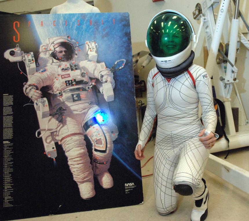
MCP spacesuits are skintight, somewhat like SCUBA (Self-Contained Underwater Breathing Apparatus) wetsuits, with a solid helmet and backpack. The backpack, helmet and hard-shell parts of the suit contain life-support, communications, navigation and computing technology.
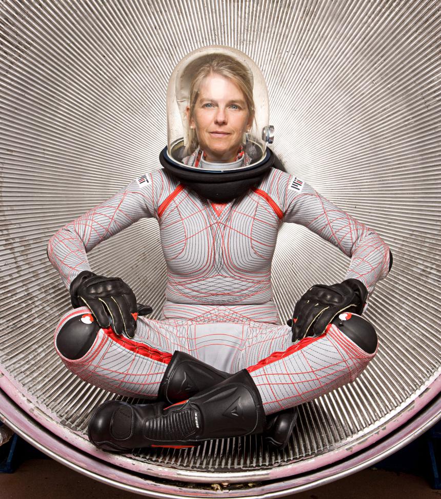
Perhaps the most advanced MCP suits currently in development are the BioSuits being researched at MIT (Massachusetts Institute of Technology) under the leadership of Dava Newman, Professor of Aeronautics and Astronautics and Engineering Systems at MIT, pictured below.
MCP suits offer important advantages over traditional gas-pressurised spacesuits:
- They provide considerably better mobility. Gas-pressurised suits are essentially a rigid balloon, and bending any of the joints requires constant force. The gloves are particularly hard to use, comparable to squeezing a tennis ball. Use of the suits is therefore rather exhausting, and the astronauts cannot work in them for long periods. MCP suits, in comparison, are much less bulky, more flexible, and easier to move around in.
- They are significantly lighter. The Apollo suits weighed 91 kg, and the new NASA Z-2 gas-pressurised spacesuits weigh 65 kg; but a fully charged BioSuit including helmet and PLSS is expected to weigh only 20 kg. On Mars, this will feel like just 7.6 kg, which is well within comfortable limits (an adult backpacker will typically carry at least 2-3 times this load). This low mass means EVAs can be longer due to reduced fatigue, and are safer due to lower inertia and therefore reduced risk of falling over. It will permit astronauts to lift and carry equipment and samples while on EVA. It also means the suits are cheaper to transport, and complete spares may be taken.
- They can provide a higher air pressure. Gas-pressurised suits typically provide very low O2 pressure in order to maximise mobility as much as possible. However, it’s unhealthy to be exposed to low O2 pressure for extended periods, which limits EVA duration. In addition, it means the astronauts need to spend lengthy periods, sometimes hours, pre-breathing pure O2 to purge N2 from their blood so that they don’t get DCS. BioSuits will provide about 35 kPa of pressure; any higher and mobility begins to be compromised. This level of pressure is much more healthful for the astronauts. Significantly, with an appropriate habitat atmosphere design, it is possible to use the suits without prebreathing, as discussed in SHAB Atmosphere.
Overall, the use MCP suits means that astronauts will be able to work outside more frequently and for longer periods, more healthfully and comfortably, and while capable of doing more useful work. These suits are an absolute necessity for Mars missions, which are long duration with an emphasis on outside work. Literally hundreds of EVAs may be required per astronaut.
Replacement parts and patch kits will be included in surface mission supplies, and the SHAB’s server will be preloaded with models of all spare parts that can be printed by a 3D printer.
11.4.2. Suit Pressure
From private communications with Prof. Dava Newman:
We’ve made some outstanding progress this semester on our active materials and believe we can now achieve the 30 kPa pressure level. It shouldn’t be asking too much for us to achieve the mid-30 kPa, especially by 2030!
A useful target pressure for the marssuits is approximately 35 kPa. As discussed in SHAB Atmosphere, this is the suit pressure needed for interoperation with the proposed habitat atmosphere, in order to establish a ZPB protocol and eliminate risk of DCS, irrespective of the number of EVAs.
According to Prof. Newman, it’s unlikely that suit pressure much higher than 35 kPa will be sought as this would begin to compromise mobility, which is the primary driver of MCP suit design. Fortunately, this is enough.
Oxygen toxicity
A suit pressure of 35 kPa is within safe limits for O2 toxicity. It has been reported (Campbell 1991) that O2 toxicity can occur when exposed to a high O2 partial pressure for an extended period; specifically, above 40.5 kPa for more than approximately 24 hours. The same report also states:
For EVAs of six to eight hours, 100 percent oxygen can be used at pressures up to 41.4 kPa (6.0 psia) with absolutely no risk.
As the proposed suit pressure falls below this threshold, oxygen toxicity is not a risk. This highlights another advantage of the MCP suit over gas-pressurised ZPB suit designs such as the new Z-2 spacesuit, which has an operating pressure of 57.2 kPa. The risk of O2 toxicity makes marssuits with O2 pressure higher than about 40 kPa less desirable for HMMs.
11.4.3. Suit Storage and Recharging
Inside both the SHAB and CAMPER will be a suit storage and recharge bay with capacity for up to six marssuits.
The suits will be powered by rechargeable graphene batteries or supercapacitors. In the suit recharge bay in the SHAB, there will be charging sockets where the suits’ battery packs can be recharged from the SHAB’s power system. In addition, hoses in the recharge bay connect the suits’ O2 tanks to the SHAB’s tanks for refilling.
Valves will be made available on the outside of the SHAB to enable refilling of marssuits tanks from the SHAB’s supplies of breathing gases, without the need to re-enter the habitat. This could be important in an emergency, such as an astronaut running very low on O2. In addition, the external valves will enable refilling of the CAMPER’s breathing gas tanks between excursions, by parking alongside the SHAB and connecting a hose.
11.5. Airlocks
Both the CAMPER and SHAB will have an airlock capable of accommodating up to two astronauts at a time. Most EVAs will involve two people, so this is a reasonable airlock size considering the need to optimise for mass, volume and time.
The B330 modules include two airlocks; one at each end.
11.5.1. Minimising Dust Migration
A feature of modern gas-pressurised spacesuit design such as the NASA Z-2 suit is the suitport, which enables spacesuits to remain outside. The suitport connects to a hatch on the side of a rover of habitat, and astronauts don the suit by climbing through the hole and into the suit. In this way the suit always remains outside and airlock operation can be avoided.
One of the primary advantages of suitports is that they prevent dust migration into the vehicle or habitat. Lunar dust that found its way into the Apollo Lunar Excursion Modules caused the astronauts to experience a number of respiratory issues, plus the dust was highly adhesive and hard to remove from suits and other surfaces.
Martian dust is different from lunar dust. Although also very fine, it is far less adhesive due to being less jagged, as erosion caused by the continual winds smooths the particles. However, it can still cause problems.
Perhaps the most serious risk associated with Martian dust is its high concentration of perchlorate, the ClO4- ion. Perchlorate inhibits thyroid function, and is therefore sometimes prescribed as a treatment for hyperthyroidism. If ingested, it can interfere with iodine uptake, hormone production and regulation of metabolism.
Martian dust may additionally cause respiratory issues; interfere with air quality, experiments, electronics, ECLSS or other SHAB systems; generally make things dirty; or cause other, unforeseen problems. Dust migration into the SHAB and CAMPER must therefore be kept to a bare minimum.
In order to mitigate dust migration into the SHAB and CAMPER, their airlocks double as suit-cleaning areas prior to re-entering.
11.5.2. Airlock Operation
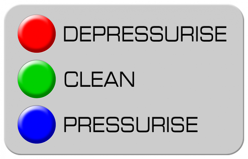
The airlock has three modes of operation, controlled by buttons aptly coloured red, green and blue:
Red: For exit. Pump breathable air out of the airlock.
Green: For entry. Dust cleaning process.
Blue: For entry. Fill the airlock with breathable air.
A wall-mounted screen shows the current pressure in the airlock, and concentrations of O2, CO2, N2 and Ar. The display indicates “SAFE” when the air in the airlock can safely be breathed. This is a precaution only, as during normal operation astronauts will breathe from their suits when inside the airlock.
Indicators on the inner and outer doors display “PRESSURE MATCH” when the airlock pressure matches either the SHAB interior pressure (~53 kPa), or the external pressure (~0.6 kPa), respectively.
The SHAB’s computer system controls airlock operation, as with all systems in the module.
Exit process
- Two crew members take their marssuits from the suit recharge bay, don them, seal the helmets and commence breathing pure O2 from the suits.
- They step into the airlock and close the inner door.
- They press the red button. If the computer cannot verify that both inner and outer door are closed, a warning is displayed. Once both doors are secure, the air is pumped out of the airlock, down through the floor vent.
- The pressure is reduced until it matches the external pressure, at which point the pressure-match indicator on the outer door will light up, and the computer will permit the outer door to be opened (this can be manually overridden in an emergency).
- The astronauts open the outer door and step out onto Mars.
Entry process
- On returning from EVA, the astronauts kick the dust off their boots and/or wipe their feet on a mat outside the entrance to the SHAB airlock.
- They open the airlock outer door, enter the airlock, and close the door.
- They press the green button. Again, the computer verifies that both doors are secure before commencing operation.
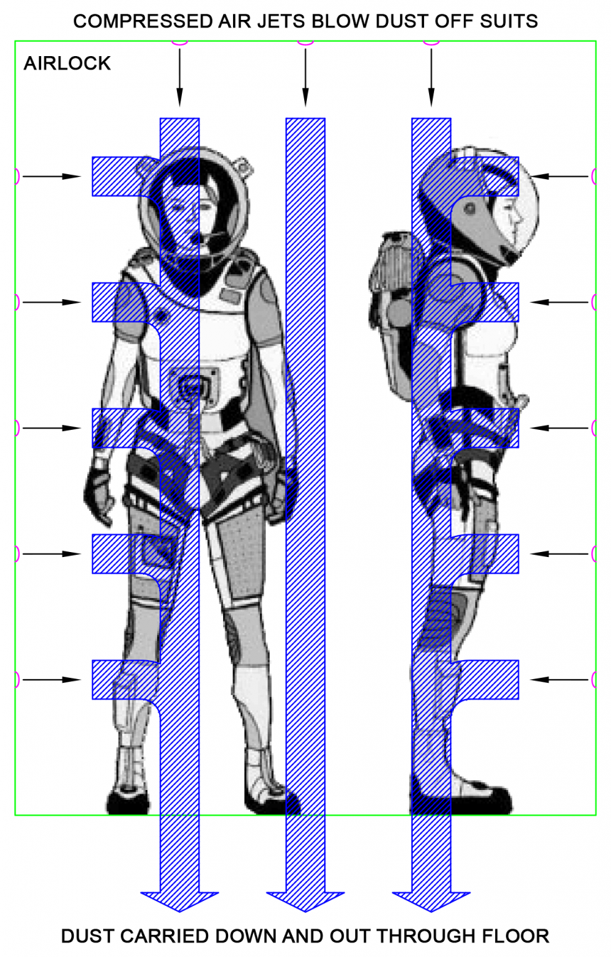
- Compressed gas is blown in through jets in the ceiling and walls, and sucked down through the floor vents, carrying away the dust and blowing it outside. This is not breathable air from the SHAB, which costs energy to make, but Martian air, which is more easily obtained. When the airlock is not in use, air is pumped in from outside, filtered, compressed and stored in a tank adjacent to the airlock for this purpose.
- The compressed air jets are supplemented by two powerful handheld vacuum cleaners with brushes, which the two astronauts use to remove any remaining dust from their own and each other’s suits. They work together to clean the suits and the airlock interior as meticulously as possible until both are fully satisfied. Despite the flow of air, the pressure does not substantially change during the cleaning process, remaining at approximately ambient Martian pressure.
- They then press the blue button. The floor vents close, and the gas from the compressed air jets switches from Martian air to breathable air from the SHAB’s tanks.
- When the pressure in the airlock matches the interior of the SHAB, the jets shut off, the pressure-match indicator on the inner door lights up, and the computer permits opening of the inner door (again, this can be manually overridden in an emergency).
- The two astronauts enter the SHAB, doff their clean marssuits, and store them in the suit recharge bay where their batteries are recharged and O2 tanks refilled.
The airlock’s dust filter is cleaned manually or automatically at the end of each EVA, or periodically as required.